Voltage Regulators
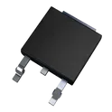
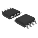
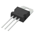
A voltage regulator is an electronic device that maintains a constant output voltage level, regardless of changes in the input voltage or load conditions. These devices are commonly used to provide a stable power supply to electronic circuits, as well as to protect them from voltage spikes and surges. There are several types of voltage regulators, including linear, switching, and pulse width modulation (PWM) regulators, each with its own set of characteristics and applications. Linear regulators, for example, are simple and efficient, but have a relatively low switching speed and can only provide a limited output current. Switching regulators, on the other hand, have higher switching speeds and can provide a higher output current, but are more complex and require additional components. In addition to their use in power supplies and voltage protection, voltage regulators are also used in a wide range of other applications, including motor control, battery charging, and instrumentation. Flux.ai has the world's largest community-driven public library of voltage regulators, with footprints, symbols, datasheets, and simulation models for a wide range of devices. Whether you're a designer, engineer, or hobbyist, you can find the resources you need to get your project up and running quickly and efficiently.
MAX20303BEWN+T
PMIC with Ultra Low IQ Voltage Regulators, Battery Charger and Fuel Gaugefor Small Lithium Ion Systems MAX20303BEWN+T is a highly integrated wearable power-management IC (PMIC) with Li-ion battery charger, fuel gauge, multiple ultra-low quiescent current DC-DC/LDO regulators, I²C interface, and a 56-bump WLP package for compact battery-powered designs. Keywords/Tags: MAX20303BEWN+T, wearable PMIC, Li-ion battery charger, fuel gauge, 56-WLP
0 Uses0 StarsTPS552892RYQR
Buck-Boost Switching Regulator IC Positive Programmable 0.8V 1 Output 8A 21-PowerVFQFN Synchronous buck-boost DC-DC converter IC that regulates output voltage from a wide input supply range for power management applications. The TPS552892RYQR integrates a four-switch synchronous buck-boost power stage and operates with a 2.7 V to 36 V input voltage range, providing a regulated output voltage across a wide conversion range. It supports programmable output voltage settings and adjustable switching frequency operation, enabling flexible power design optimization. The device includes I²C interface control for configuration and telemetry monitoring. It is designed for high-efficiency step-up and step-down conversion in compact power systems. Key specifications (per datasheet): Input voltage range: 2.7 V to 36 V Topology: Synchronous 4-switch buck-boost converter Control/interface: I²C configurable operation Adjustable switching frequency (as specified in datasheet) #DC-DCConverter #BuckBoost #PowerManagement #TexasInstruments #SynchronousConverter #IC
35 Uses0 StarsLT3641EFE#PBF
Buck Switching Regulator IC Positive Adjustable 0.6V, 1.265V 2 Output 1.3A, 1.1A 28-TSSOP (0.173", 4.40mm Width) Exposed Pad The LT3641EFE#PBF specification defines the engineering requirements for a dual-channel step-down switching regulator integrated circuit designed for high-efficiency power conversion and distribution applications. This specification establishes the functional, electrical, mechanical, thermal, environmental, and quality requirements necessary to ensure stable voltage regulation, efficient power delivery, and long-term operational reliability in industrial, embedded, communication, and control systems. The device is intended for use in distributed power architectures, industrial automation equipment, instrumentation, telecommunications systems, automotive electronics, and embedded applications requiring multiple regulated output voltages from a common input source. The integrated dual-channel architecture enables compact power supply designs while providing high conversion efficiency, low power dissipation, and reliable performance across a wide range of operating conditions. Engineering Requirements The switching regulator shall be manufactured using qualified semiconductor fabrication processes and high-quality materials to ensure consistent electrical performance, efficient power conversion, and dependable long-term reliability. The device shall maintain stable operation under specified input voltage, output load, temperature, and environmental operating conditions. Electrical characteristics shall provide accurate output voltage regulation, high conversion efficiency, low output ripple, and fast transient response. The regulator shall maintain stable switching behavior during startup, shutdown, load variations, and input voltage fluctuations while ensuring reliable power delivery to connected circuits. The integrated control architecture shall support independent regulation of multiple output channels and provide reliable operation during dynamic system conditions. Built-in protection functions shall support safe operation during abnormal events including overload, short-circuit, thermal stress, and fault conditions, thereby enhancing overall system reliability. Thermal performance shall support continuous operation within the specified junction temperature range while maintaining electrical integrity and long-term reliability. The package shall facilitate effective heat dissipation and shall be suitable for automated surface-mount assembly and standard solder reflow manufacturing processes. Mechanical construction shall withstand thermal cycling, vibration, mechanical handling, and environmental exposure without degradation of electrical or structural performance. Workmanship shall be free from defects including contamination, package cracking, bond failures, lead deformation, or structural inconsistencies that could adversely affect functionality or reliability. Inspection, validation, and testing shall be performed using calibrated equipment and controlled quality procedures to verify compliance with engineering and manufacturing requirements. Any deviation from this specification shall require formal engineering evaluation, documented technical justification, and approval through the established engineering change control process before implementation. Documentation Supporting documentation shall include engineering drawings, electrical performance specifications, thermal characterization reports, application guidelines, qualification records, inspection reports, reliability data, material declarations, and revision-controlled manufacturing documentation. All documentation shall be maintained under formal configuration management and quality assurance systems to ensure complete product traceability. Revision Control Any modification to this specification shall be managed through the formal engineering change management process. All revisions shall undergo technical review, validation, and approval before release to ensure continued compliance with design intent and applicable engineering standards. #EngineeringSpecification #SwitchingRegulator #BuckConverter #PowerManagement #DCDCConverter #PowerElectronics #EmbeddedSystems #IndustrialElectronics #QualityAssurance #EngineeringDocumentation
0 Uses0 StarsXAL6060-682MEC
6.8 µH Shielded Molded Inductor 9 A 20.8mOhm Nonstandard The XAL6060-682MEC specification defines the engineering requirements for a shielded surface-mount power inductor designed for high-efficiency energy storage and power conversion applications. This specification establishes the functional, electrical, mechanical, thermal, environmental, and quality requirements necessary to ensure stable inductance characteristics, efficient current handling, low electromagnetic interference, and long-term operational reliability. The component is intended for use in DC-DC converters, voltage regulator modules, power management systems, industrial automation equipment, automotive electronics, telecommunications infrastructure, and embedded electronic applications requiring compact, high-current inductive components. The magnetically shielded construction minimizes stray magnetic fields while supporting efficient switching performance and stable energy transfer in high-frequency power circuits. Engineering Requirements The power inductor shall be manufactured using high-quality magnetic core materials and precision-wound conductors to ensure consistent inductance, low core losses, and dependable long-term reliability. The construction shall maintain stable electrical and magnetic characteristics throughout the specified operating voltage, current, frequency, and temperature ranges. Electrical characteristics shall provide accurate inductance, low direct current resistance, high saturation current capability, and low core loss to maximize power conversion efficiency. The component shall maintain stable performance during continuous operation, transient load conditions, and dynamic switching without significant degradation of inductance or current-handling capability. The shielded magnetic structure shall minimize electromagnetic emissions and magnetic coupling with adjacent components while improving electromagnetic compatibility in densely populated printed circuit board assemblies. Thermal performance shall support efficient heat dissipation and continuous operation within the specified operating temperature range while maintaining electrical integrity and structural stability. Mechanical construction shall be suitable for automated surface-mount assembly and compatible with standard solder reflow manufacturing processes. The package shall withstand thermal cycling, vibration, mechanical shock, and handling without degradation of electrical or mechanical performance. Workmanship shall be free from defects including cracks, contamination, core damage, winding irregularities, plating defects, or structural inconsistencies that could adversely affect functionality or reliability. Inspection, validation, and testing shall be conducted using calibrated equipment and controlled quality procedures to verify compliance with all applicable engineering and manufacturing requirements. Any deviation from this specification shall require formal engineering evaluation, documented technical justification, and approval through the established engineering change control process before implementation. Documentation Supporting documentation shall include engineering drawings, electrical performance specifications, magnetic characterization reports, thermal performance data, qualification records, inspection reports, material declarations, reliability data, and revision-controlled manufacturing documentation. All documentation shall be maintained under formal configuration management and quality assurance systems to ensure complete product traceability. Revision Control Any modification to this specification shall be managed through the formal engineering change management process. All revisions shall undergo technical review, validation, and approval before release to ensure continued compliance with design intent and applicable engineering standards. #EngineeringSpecification #PowerInductor #ShieldedInductor #PowerElectronics #DCDCConverter #PowerManagement #Magnetics #IndustrialElectronics #QualityAssurance #EngineeringDocumentation
0 Uses0 Stars