Oscillators
PCA9685PW,118
LED Driver IC 16 Output Linear PWM Dimming 25mA 5.5V 28-TSSOP PCA9685PW,118 is a 16-channel, 12-bit PWM LED controller with an I²C interface designed for LED dimming, RGB/RGBA lighting, and servo motor control applications. It provides independent PWM control for up to 16 outputs, allowing precise brightness or position control while minimizing MCU GPIO usage. The device supports Fast-mode Plus I²C communication up to 1 MHz and operates from a 2.3 V to 5.5 V supply range. It is commonly used in robotics, LED backlighting, automation systems, and PWM expansion modules for microcontrollers such as Arduino, ESP32, and Raspberry Pi. Key Features 16 independent PWM output channels 12-bit PWM resolution (4096 steps) Programmable PWM frequency from approximately 24 Hz to 1526 Hz I²C Fast-mode Plus compatible interface up to 1 MHz Six hardware address pins allowing up to 62 devices on one I²C bus Programmable open-drain or totem-pole outputs Output capability: 25 mA sink current 10 mA source current Internal 25 MHz oscillator with optional external clock input Individual programmable LED ON/OFF timing for reduced EMI and current surges Supports software reset and group addressing (All Call/Sub Call) 5.5 V tolerant inputs and outputs Operating voltage range: 2.3 V to 5.5 V Package: 28-pin TSSOP (PW suffix) #CommonPartsLibrary #IntegratedCircuit #PowerManagement #LEDdriver
72 Uses
1 Star
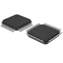
STM32F405RGT6
ARM® Cortex®-M4 series Microcontroller IC 32-Bit Single-Core 168MHz 1MB (1M x 8) FLASH 64-LQFP (10x10) Arm® Cortex®-M4 32b MCU+FPU, 210DMIPS, up to 1MB flash/192+4KB RAM, USB OTG HS/FS, Ethernet, 17 TIMs, 3 ADCs, 15 comm. interfaces, and camera Includes ST state-of-the-art patented technology • Core: Arm® 32-bit Cortex®-M4 CPU with FPU, Adaptive real-time accelerator (ART Accelerator) allowing 0-wait state execution from flash memory, frequency up to 168 MHz, memory protection unit, 210 DMIPS/ 1.25 DMIPS/MHz (Dhrystone 2.1), and DSP instructions • Memories – Up to 1 Mbyte of flash memory – Up to 192+4 Kbytes of SRAM including 64- Kbyte of CCM (core coupled memory) data RAM – 512 bytes of OTP memory – Flexible static memory controller supporting CompactFlash™, SRAM, PSRAM, NOR and NAND memories • LCD parallel interface, 8080/6800 modes • Clock, reset, and supply management – 1.8 V to 3.6 V application supply and I/Os – POR, PDR, PVD and BOR – 4-to-26 MHz crystal oscillator – Internal 16 MHz factory-trimmed RC (1% accuracy) – 32 kHz oscillator for RTC with calibration – Internal 32 kHz RC with calibration • Low-power operation – Sleep, Stop, and Standby modes –VBAT supply for RTC, 20×32-bit backup registers + optional 4 KB backup SRAM • 3×12-bit, 2.4 MSPS A/D converters: up to 24 channels and 7.2 MSPS in triple interleaved mode • 2×12-bit D/A converters • General-purpose DMA: 16-stream DMA controller with FIFOs and burst support • Up to 17 timers: up to twelve 16-bit and two 32- bit timers up to 168 MHz, each with up to 4 IC/OC/PWM or pulse counter and quadrature (incremental) encoder input • Debug mode – Serial wire debug (SWD) & JTAG interfaces – Cortex-M4 Embedded Trace Macrocell™ • Up to 140 I/O ports with interrupt capability – Up to 136 fast I/Os up to 84 MHz – Up to 138 5 V-tolerant I/Os • Up to 15 communication interfaces – Up to 3 × I2C interfaces (SMBus/PMBus) – Up to 4 USARTs/2 UARTs (10.5 Mbit/s, ISO 7816 interface, LIN, IrDA, modem control) – Up to 3 SPIs (42 Mbits/s), 2 with muxed full-duplex I2S to achieve audio class accuracy via internal audio PLL or external clock – 2 × CAN interfaces (2.0B Active) – SDIO interface • Advanced connectivity – USB 2.0 full-speed device/host/OTG controller with on-chip PHY – USB 2.0 high-speed/full-speed device/host/OTG controller with dedicated DMA, on-chip full-speed PHY and ULPI – 10/100 Ethernet MAC with dedicated DMA: supports IEEE 1588v2 hardware, MII/RMII #commonpartslibrary #integratedcircuit #microcontroller
56 Uses
1 Star
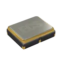
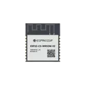
ESP32-C3-WROOM-02-N4
Bluetooth, WiFi 802.11b/g/n, Bluetooth v5.0 Transceiver Module 2.4GHz PCB Trace Surface Mount The ESP32-C3-WROOM-02-N4 is a compact, general-purpose Wi-Fi and Bluetooth Low Energy (BLE) module developed by Espressif Systems. It is built around the ESP32-C3 SoC and integrates RF components, crystal oscillator, flash memory, and PCB antenna in a single module. It is designed for a wide range of applications such as IoT devices, smart home systems, industrial automation, and consumer electronics, offering a balance of performance, low power consumption, and cost efficiency. Key Features MCU & Memory 32-bit RISC-V single-core processor up to 160 MHz 384 KB ROM 400 KB SRAM + 8 KB RTC SRAM Integrated 4 MB SPI flash (N4 variant) Connectivity 2.4 GHz Wi-Fi (802.11 b/g/n) Supports Station, SoftAP, and Station + SoftAP modes Bluetooth 5 (BLE) with mesh support Data rates up to 150 Mbps (Wi-Fi) Peripherals & Interfaces Up to 15 GPIOs Interfaces: SPI, UART, I2C, I2S LED PWM ADC (SAR) Timers & watchdog USB Serial/JTAG support TWAI® (CAN 2.0 compatible) #commonpartslibrary #transceiver #module #wireless #rf
936 Uses
1 Star

Arduino Nano Barebones - SMD No Header
Important Note: You must connect your own SPI/ICSP programming header if you want to burn the Arduino bootloader to the MCU. In this version, you must also provide your own UART interface. SMD Manufacturing: Need a hotplate and solderpaste Good to haves: - Oscillator Decoupling Caps Expose UART via connector Programming Button Onboard LED Reset Button You don't have to populate everything! Only these are mandatory: Reset Button Find the reference schematic here: https://www.arduino.cc/en/uploads/Main/ArduinoNano30Schematic.pdf
78 Uses
1 Star

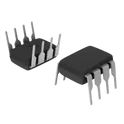
CH9101N
USB to Serial Port Chip CH9101 CH9101N is a high-speed USB-to-UART bridge IC developed by WCH (Qinheng Electronics). It converts a USB 2.0 Full-Speed interface into a standard asynchronous UART serial interface, enabling seamless communication between a computer and microcontrollers, embedded systems, industrial equipment, and other UART-based devices. The device features an integrated clock oscillator and power-on reset circuitry, minimizing external components and simplifying PCB design. Housed in a compact SOP-8 package, the CH9101N supports UART logic voltages from 1.8 V to 5 V, making it suitable for a wide range of low-power and mixed-voltage applications. It is commonly used for USB debugging, firmware downloading, serial communication, and IoT development. Key Features USB 2.0 Full-Speed compliant device interface USB-to-UART bridge with baud rates up to 3 Mbps Supports 1.8 V, 2.5 V, 3.3 V, and 5 V UART I/O levels Integrated clock oscillator (no external crystal required) Built-in power-on reset circuitry Full-duplex UART communication Supports hardware flow control (RTS/CTS) Compatible with standard virtual COM port (VCP) drivers Compact SOP-8 package with minimal external components Suitable for MCU programming, debugging, and serial communication applications #CH9101N #WCH #USBtoUART #USBBridge #UART #USB20 #SerialCommunication #EmbeddedSystems #Microcontroller #IoT #IndustrialAutomation #Debugging #FirmwareDownload #SOP8 #InterfaceIC
0 Uses
0 Stars
CMX973Q5
RF Demodulator IC 20MHz ~ 300MHz 32-VFQFN Exposed Pad The CMX973Q5 specification defines the engineering requirements for a radio frequency quadrature modulator integrated circuit designed for digital and analog wireless communication systems. This specification establishes the functional, electrical, mechanical, thermal, environmental, and quality requirements necessary to ensure accurate signal modulation, high RF performance, and long-term operational reliability. The device is intended for use in wireless communication equipment, telemetry systems, software-defined radio platforms, digital data transmission equipment, industrial RF systems, and embedded communication applications requiring high-performance I/Q modulation. It provides precise conversion of baseband in-phase and quadrature signals into modulated RF output while maintaining excellent signal integrity, low distortion, and stable operation over a wide range of operating conditions. Engineering Requirements The RF modulator shall be manufactured using qualified semiconductor fabrication processes and high-quality materials to ensure consistent electrical characteristics, reliable modulation accuracy, and dependable long-term performance. The device shall maintain stable operation under specified supply voltage, temperature, and environmental operating conditions. Electrical characteristics shall provide accurate in-phase and quadrature signal processing, low phase imbalance, high linearity, low noise, and excellent carrier suppression. The device shall maintain stable RF output characteristics and predictable modulation performance throughout continuous operation while minimizing harmonic distortion and unwanted spurious emissions. The integrated RF architecture shall support efficient signal conversion and reliable interface with external oscillators, filters, and communication circuitry. The device shall preserve signal integrity across the specified operating frequency range while supporting high-quality modulation for digital and analog communication protocols. Thermal performance shall support continuous operation within the specified junction temperature range while maintaining electrical integrity and long-term reliability. The package shall be suitable for automated surface-mount assembly and compatible with standard solder reflow manufacturing processes. Mechanical construction shall withstand thermal cycling, vibration, mechanical handling, and environmental exposure without degradation of electrical or mechanical performance. Workmanship shall be free from defects including contamination, package cracking, bond failures, lead deformation, plating irregularities, or structural inconsistencies that could adversely affect RF performance or reliability. Inspection, validation, and testing shall be performed using calibrated RF measurement equipment and controlled quality procedures to verify compliance with engineering and manufacturing requirements. Any deviation from this specification shall require formal engineering evaluation, documented technical justification, and approval through the established engineering change control process before implementation. Documentation Supporting documentation shall include engineering drawings, RF performance specifications, modulation characteristics, application guidelines, qualification reports, inspection records, reliability data, material declarations, and revision-controlled manufacturing documentation. All documentation shall be maintained under formal configuration management and quality assurance systems to ensure complete product traceability. Revision Control Any modification to this specification shall be managed through the formal engineering change management process. All revisions shall undergo technical review, validation, and approval before release to ensure continued compliance with design intent and applicable engineering standards. #EngineeringSpecification #RFModulator #QuadratureModulator #WirelessCommunication #RFIC #SignalModulation #EmbeddedSystems #Telecommunications #QualityAssurance #EngineeringDocumentation
0 Uses
0 Stars
SMV1705-079LF
Varactors Single 12 V Surface Mount SC-79 The SMV1705-079LF specification defines the engineering requirements for a hyperabrupt junction varactor diode designed for voltage-controlled capacitance applications in radio frequency and high-frequency electronic systems. This specification establishes the functional, electrical, mechanical, thermal, environmental, and quality requirements necessary to ensure stable capacitance tuning, reliable RF performance, and long-term operational stability. The device is intended for use in voltage-controlled oscillators, frequency synthesizers, RF tuning circuits, phase-locked loops, wireless communication equipment, and other applications requiring electronically adjustable capacitance. The varactor diode provides predictable capacitance variation as a function of reverse bias voltage, enabling accurate frequency control and signal tuning while maintaining low loss and high reliability. Engineering Requirements The varactor diode shall be manufactured using qualified semiconductor fabrication processes and high-quality materials to ensure consistent capacitance characteristics, low leakage current, and dependable long-term reliability. The device shall maintain stable operation under specified electrical, thermal, and environmental operating conditions. Electrical characteristics shall provide predictable capacitance variation with reverse bias voltage, low series resistance, and high quality factor suitable for radio frequency operation. The device shall maintain stable tuning characteristics, low distortion, and consistent performance across the specified operating frequency and temperature ranges. The semiconductor structure shall support reliable RF operation while minimizing parasitic effects that could degrade tuning accuracy or signal integrity. The device shall exhibit repeatable capacitance characteristics throughout continuous operation and under varying environmental conditions. Thermal performance shall support continuous operation within the specified junction temperature range while maintaining electrical integrity and long-term reliability. The package shall be suitable for automated surface-mount assembly and compatible with standard solder reflow manufacturing processes. Mechanical construction shall withstand thermal cycling, vibration, mechanical handling, and environmental exposure without degradation of electrical or mechanical performance. Workmanship shall be free from defects including contamination, package cracking, bond failures, lead deformation, plating irregularities, or structural inconsistencies that could adversely affect functionality or reliability. Inspection, validation, and testing shall be performed using calibrated equipment and controlled quality procedures to verify compliance with engineering and manufacturing requirements. Any deviation from this specification shall require formal engineering evaluation, documented technical justification, and approval through the established engineering change control process before implementation. Documentation Supporting documentation shall include engineering drawings, electrical performance specifications, RF characterization reports, qualification records, inspection reports, reliability data, material declarations, and revision-controlled manufacturing documentation. All documentation shall be maintained under formal configuration management and quality assurance systems to ensure complete product traceability. Revision Control Any modification to this specification shall be managed through the formal engineering change management process. All revisions shall undergo technical review, validation, and approval before release to ensure continued compliance with design intent and applicable engineering standards. #EngineeringSpecification #VaractorDiode #RFComponents #FrequencyTuning #VoltageControlledCapacitance #WirelessCommunication #Semiconductor #SignalIntegrity #QualityAssurance #EngineeringDocumentation
0 Uses
0 Stars