Inductors
An inductor is an electronic component that stores energy in the form of a magnetic field when an electric current flows through it. It is used in a variety of applications, including filters, oscillators, and power supply circuits. One of the main use cases for inductors is to block the flow of direct current (DC) while allowing alternating current (AC) to pass through. This makes them useful for filtering out unwanted frequencies or for blocking DC signals in AC circuits. Inductors are also used in oscillator circuits to create a sustained AC signal and in power supply circuits to smooth out voltage fluctuations. Flux.ai is home to the world's largest community-driven public library of inductors, featuring footprints, symbols, datasheets, and simulation models. Whether you are a professional engineer or a hobbyist, Flux.ai has the resources you need to design and build electronic circuits that include inductors.
MPL-AY1265-2R2
2.2µH Unshielded Molded Inductor 17 A 3.7mOhm 2-SMD, J-Lead The MPL-AY1265-2R2 is a 2.2 µH surface-mount molded power inductor from Monolithic Power Systems (MPS). It is designed for high-current DC-DC switching power supplies and power management applications requiring low DC resistance (DCR), high efficiency, and stable inductance over a wide operating temperature range. Its molded construction minimizes audible noise and provides excellent mechanical reliability for compact, high-performance electronic designs. Key Features 2.2 µH inductance with ±20% tolerance High rated current: up to 17 A Low DC resistance: 3.7 mΩ typ. (4.3 mΩ max.) Soft saturation characteristics for improved reliability Molded construction for enhanced durability and reduced EMI Low audible noise during switching operation Stable performance across a wide temperature range Operating temperature: −40°C to +155°C Compact SMD package: 13.5 × 12.6 × 6.2 mm RoHS/REACH compliant and halogen-free Typical Applications Battery-powered devices Portable electronics Embedded computing systems High-current switching mode power supplies (SMPS) High-frequency DC-DC converters Point-of-load (POL) converters FPGA power rails #MoldedInductor #PowerInductor #2_2uH #HighCurrent #LowDCR #SMPS #DCDCConverter #PowerManagement #SMD #MonolithicPowerSystems #RoHS #EmbeddedSystems
4 Uses0 StarsXAL1010-103MED
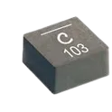
10 µH Shielded Molded Inductor 15.5 A 14.75mOhm Max Nonstandard The XAL1010-103MED specification defines the engineering requirements for a shielded power inductor designed for high-efficiency energy storage and power conversion applications. This specification establishes the functional, electrical, mechanical, thermal, environmental, and quality requirements necessary to ensure stable inductance characteristics, efficient current handling, and long-term operational reliability in power electronic systems. The component is intended for use in DC-DC converters, voltage regulators, power management circuits, industrial control equipment, automotive electronics, and embedded systems requiring compact, high-current inductive components. The magnetically shielded construction minimizes electromagnetic interference while supporting efficient energy transfer and stable performance in high-frequency switching applications. Engineering Requirements The power inductor shall be manufactured using high-quality magnetic core materials and precision-wound conductors to ensure consistent inductance, low core losses, and reliable current-carrying capability. The construction shall maintain stable electrical performance under specified operating voltage, current, frequency, and temperature conditions. Electrical characteristics shall provide accurate inductance values, low direct current resistance, high saturation current capability, and low electromagnetic emissions. The component shall maintain stable performance during continuous operation, transient loading, and thermal cycling without significant degradation of inductance or efficiency. Thermal performance shall support effective heat dissipation and continuous operation within the specified temperature range while maintaining structural integrity and electrical characteristics. The shielded construction shall minimize magnetic field leakage and improve electromagnetic compatibility within densely populated electronic assemblies. Mechanical construction shall be suitable for surface-mount assembly and compatible with automated manufacturing processes. The component shall withstand solder reflow, vibration, mechanical shock, and handling without deformation or degradation of electrical performance. Workmanship shall be free from defects including cracks, contamination, core damage, winding irregularities, or structural inconsistencies. Inspection, validation, and testing shall be conducted using calibrated equipment and controlled quality procedures to verify compliance with all applicable engineering and manufacturing requirements. Any deviation from this specification shall require formal engineering evaluation, documented technical justification, and approval through the established engineering change control process. Documentation Supporting documentation shall include engineering drawings, electrical specifications, magnetic characterization data, thermal performance reports, qualification records, inspection reports, material declarations, and revision-controlled manufacturing documentation. All documentation shall be maintained under formal configuration management and quality assurance systems to ensure complete product traceability. Revision Control Any modification to this specification shall be managed through the formal engineering change management process. All revisions shall undergo technical review, validation, and approval before implementation to ensure continued compliance with design intent and applicable engineering standards. #EngineeringSpecification #PowerInductor #ShieldedInductor #PowerElectronics #DCDCConverter #PowerManagement #Magnetics #IndustrialElectronics #QualityAssurance #EngineeringDocumentation #CommonPartsLibrary #Inductor #XAL1010
0 Uses0 StarsXFL4020-152MEC
1.5µH Shielded Molded Inductor 9.1A 15.8mOhm Max 1616 (4040 Metric) The XFL4020-152MEC is a metal-composite core, shielded surface-mount power inductor with an inductance value of 1.5 µH and a current rating of 9.1 A. Its low DCR of 15.8 mΩ maximum helps reduce conduction losses, making it suitable for efficient power conversion designs. The component is rated for automotive-grade reliability (AEC-Q200) and operates over a wide temperature range of -40°C to +125°C. Key Features Inductance: 1.5 µH Tolerance: ±20% Maximum Current Rating: 9.1 A Saturation Current (Isat): Approximately 4.6 A Low DC Resistance (DCR): 15.8 mΩ max Shielded molded construction for reduced EMI radiation Metal composite core for high efficiency and compact size Surface-mount package: 1616 / 4040 metric Dimensions: approximately 4.0 mm × 4.0 mm × 2.1 mm Self-resonant frequency: 59 MHz AEC-Q200 qualified for automotive applications Operating temperature: -40°C to +125°C Typical Applications DC/DC switching converters Power supply filtering Voltage regulator modules (VRM) Battery-powered devices Automotive power electronics Embedded power management systems Hashtags #Coilcraft #XFL4020 #PowerInductor #ShieldedInductor #SMTInductor #DC_DCConverter #PowerElectronics #AutomotiveElectronics #AECQ200 #PCBDesign #ElectronicComponents #commonpartslibrary #inductor
65 Uses0 StarsXFL4015-471MEC
470 nH Shielded Molded Inductor 9.1 A 8.36mOhm Max 1616 (4040 Metric) The XFL4015-471MEC specification establishes the engineering requirements for the designated electronic component, defining its intended functionality, mechanical characteristics, electrical performance, material requirements, manufacturing quality, and inspection criteria. This specification serves as the primary technical reference to ensure the component consistently meets design expectations, operational reliability, and applicable industry standards throughout production and field use. Engineering Requirements The component shall be manufactured using approved materials and controlled production processes to ensure consistent electrical and mechanical performance. All dimensions, tolerances, and physical characteristics shall conform to the latest approved engineering documentation. The component shall be suitable for its intended operating environment and shall maintain performance within the specified electrical and environmental conditions. Workmanship shall be free from defects including cracks, contamination, corrosion, deformation, or any condition that could adversely affect reliability or functionality. All manufacturing and inspection processes shall be performed using calibrated equipment and verified in accordance with established quality management procedures. Testing and validation shall confirm compliance with electrical, mechanical, and environmental performance requirements prior to product acceptance. Any deviation from this specification shall require formal engineering review, documented approval, and appropriate revision control before implementation. Documentation Supporting documentation shall include engineering drawings, material certifications, inspection reports, test records, process documentation, and revision-controlled manufacturing specifications. All documentation shall be maintained in accordance with the organization's quality management and document control requirements. Revision Control Changes to this specification shall be managed through the approved engineering change process to ensure traceability, technical accuracy, and continued compliance with applicable design and quality requirements. #EngineeringSpecification #TechnicalSpecification #ElectronicComponents #ElectricalEngineering #QualityControl #Manufacturing #EngineeringDocumentation #Compliance
29 Uses0 Stars