Top User Components
Discover the most popular and effective components used in cutting-edge PCB designs on Flux.ai. This collection showcases the components that have been integral to the success of our community's most innovative printed circuit board designs. Ranging from simple resistors to complex integrated circuits, these components represent the best in terms of functionality, reliability, and performance. It’s a treasure trove for anyone looking to enhance their PCB layout and designs with proven, high-quality components. It's an excellent resource for gaining insights into the component preferences of skilled designers and understanding why certain components stand out in the realm of electronic design. Whether you're refining your current project or starting a new one, these components offer valuable inspiration and a benchmark for quality. By spotlighting the components chosen by our top users, Flux.ai not only celebrates the ingenuity of its community but also fosters a culture of sharing and learning. This subcategory is a testament to the collaborative spirit at Flux.ai, encouraging continuous improvement and exploration in electronic component selection.
Realistic Brown Battle Mech
Nice — you can do a clean pulse + latch using a single quad Schmitt-NAND chip: 74HC132 (or 74LVC132 for 3.3 V systems). The HC132 contains four 2-input NAND gates with Schmitt inputs so you can both clean a noisy SYN480R DATA line and build an SR latch (NAND SR is active-LOW) inside one package. Only a few passives and a driver transistor are needed. Below is a ready-to-build recipe (parts, wiring, explanation, tuning tips, and an ASCII schematic) — no extra logic ICs required. Parts (per latch) 1 × 74HC132 (quad 2-input NAND with Schmitt inputs). If your system is 3.3 V use 74LVC132 / 74HC132 rated for 3.3 V. Rin = 47 kΩ (input series) Cfilter = 10 nF (input RC to ground) — tweak for debounce/clean time Rpulldown = 100 kΩ (pull-down at input node, optional) Rpullup = 100 kΩ (pull-up for active-LOW R input so reset is idle HIGH) Rbase = 10 kΩ, Q = 2N2222 (NPN) or small N-MOSFET (2N7002) to drive your load Diode for relay flyback (1N4001) if you drive a coil Optional small cap 0.1 µF decoupling at VCC of IC Concept / how it works (short) Use Gate1 (G1) of 74HC132 as a Schmitt inverter by tying its two inputs together and feeding a small RC filter from SYN480R.DATA. This removes HF noise and provides a clean logic transition. Because it's a NAND with tied inputs its function becomes an inverter with Schmitt behavior. Use G2 & G3 as the cross-coupled NAND pair forming an SR latch (active-LOW inputs S̄ and R̄). A low on S̄ sets Q = HIGH. A low on R̄ resets Q = LOW. Wire the cleaned/inverted output of G1 to S̄. A valid received pulse (DATA high) produces a clean LOW on S̄ (because G1 inverts), setting the latch reliably even if the pulse is brief. R̄ is your reset input (pushbutton, HT12D VT, MCU line, etc.) — idle pulled HIGH. Q drives an NPN/MOSFET to switch your load (relay, LED, etc.). Recommended wiring (pin mapping, assume one chip; use datasheet pin numbers) I’ll refer to the 4 gates as G1, G2, G3, G4. Use G4 optionally for additional conditioning or to build a toggler later. SYN480R.DATA --- Rin (47k) ---+--- Node A ---||--- Cfilter (10nF) --- GND | Rpulldown (100k) --- GND (optional, keeps node low) Node A -> both inputs of G1 (tie inputs A and B of Gate1 together) G1 output -> S̄ (S_bar) (input1 of Gate2) Gate2 (G2): inputs = S̄ and Q̄ -> output = Q Gate3 (G3): inputs = R̄ and Q -> output = Q̄ R̄ --- Rpullup (100k) --- VCC (reset is idle HIGH; pull low to reset) (optional) R̄ can be wired to a reset pushbutton to GND or to an MCU pin Q -> Rbase (10k) -> base of 2N2222 (emitter GND; collector to one side of relay coil) Other side of relay coil -> +V (appropriate coil voltage) Diode across coil If you prefer MOSFET low side switching: Q -> gate resistor 100Ω -> gate of 2N7002 2N7002 source -> GND ; drain -> relay coil low side
0 Uses1 StarsESP32 Robot Controller | AI Design Review Tutorial [Example] fukm
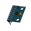
Spot the mistake! Learn how to use AI to conduct a design review on an ESP32-based control board. This project is ideal for autonomous or radio-controller robots featuring inputs for sensors, encoders, and a Flysky RC receiver, plus an I2C display for configuration.
0 Uses1 StarsBrainstorm a new project with AI [Example]
1. Empieza con el objetivo Ejemplo: “Estoy creando un módulo de control para una bomba de aire de 24 V en una máquina CNC láser. El circuito debe encender y apagar la bomba según la señal FAN que viene de la tarjeta de control (3.3 V o 5 V).” 2. Explica los requerimientos La bomba trabaja a 24 V y hasta 2 A. El control debe ser con un MOSFET N–channel en conmutación. Debe incluir protección contra picos y ruidos eléctricos. Se deben mostrar indicadores LED (encendido, funcionamiento, error). 3. Lista de funciones que quieres en el diseño Protección: fusible, diodo flyback, TVS, snubber RC. Control: MOSFET con resistencia de gate y pull-down. Filtrado: capacitores cerca de la bomba. Indicadores LED: Azul: energía 24 V presente. Verde: bomba activa. Rojo: error o apagado. 4. Explica la lógica de funcionamiento (qué debe pasar) Cuando la fuente 24 V se conecta → LED azul enciende. Cuando la señal FAN activa el MOSFET → bomba enciende + LED verde enciende. Cuando la bomba está apagada → LED rojo puede encender (opcional). Si ocurre sobrecorriente → el fusible abre el circuito. 5. Diagrama de bloques sencillo (texto) [FUENTE 24V] -- [FUSIBLE] --+--> [BOMBA] --> [MOSFET] --> GND | +--> [LED Azul] --> GND [SALIDA FAN] --> [Res 100Ω] --> [Gate MOSFET] [Gate MOSFET] --> [Pull-down 100kΩ a GND] [Protecciones: Diodo, TVS, RC, Capacitores en paralelo con la bomba]
0 Uses1 Stars
Arduino Pro Micro
The Micro is a microcontroller board based on the ATmega32U4 (datasheet), developed in conjunction with Adafruit. It has 20 digital input/output pins (of which 7 can be used as PWM outputs and 12 as analog inputs), a 16 MHz crystal oscillator, a micro USB connection, an ICSP header, and a reset button. It contains everything needed to support the microcontroller; simply connect it to a computer with a micro USB cable to get started. It has a form factor that enables it to be easily placed on a breadboard. The Micro board is similar to the Arduino Leonardo in that the ATmega32U4 has built-in USB communication, eliminating the need for a secondary processor. This allows the Micro to appear to a connected computer as a mouse and keyboard, in addition to a virtual (CDC) serial / COM port.
0 Uses1 StarsFast Silver Flubber
Create a schematic diagram of an electric fence controller using the NE556 dual timer IC. The circuit must include all components with clear electronic symbols (resistors, capacitors, transistors, diode, relay) connected by lines as in a real circuit diagram. Specifications: 1. Power supply: - Vcc = +12V connected to pin 14 of the NE556. - Pin 1 of the NE556 to ground. 2. Timer A (active 10 seconds): - Pin 2 (Trigger A) receives a pulse from transistor Q2 (contact detector). - Pin 6 (Threshold A) connected to Pin 7 (Discharge A). - R1 = 1 MΩ between Pin 7 and +12V. - C1 = 10 µF between Pin 6 and ground. - Pin 3 (Out A) goes through a 4.7 kΩ resistor to the base of Q1 (BC547 NPN transistor). - Pin 3 also connected via a 100 nF capacitor to Pin 13 (Trigger B of Timer B). 3. Timer B (rest 10 seconds): - Pin 9 (Discharge B) and Pin 8 (Threshold B) connected together. - R2 = 1 MΩ between Pin 9 and +12V. - C2 = 10 µF between Pin 8 and ground. - Pin 12 (Out B) can be optionally used to block retrigger of Timer A. 4. Relay driver stage: - Q1 = BC547 NPN transistor. - Base connected through 4.7 kΩ resistor to Pin 3 (Out A). - Emitter to ground. - Collector connected to one side of the relay coil. - Other side of relay coil connected to +12V. - A diode 1N4007 placed in parallel with the relay coil (cathode to +12V, anode to collector of Q1). - Relay contacts switch the +12V supply to the electric fence energizer. 5. Contact detector: - Shunt resistor ≈0.1 Ω placed in series with the fence output. - Q2 = BC547 NPN transistor, base connected to the shunt, emitter to ground, collector to Pin 2 (Trigger A). - When current flows through the shunt, Q2 provides a trigger pulse to Timer A. Please draw the schematic in a standard style with components connected by straight lines, not in block diagrams. Show clear pin numbers of the NE556 and all external components.
0 Uses1 StarsWily Orange TARDIS
Objetivo: leer coordenadas X/Y en un panel resistivo casero con Arduino Nano. Componentes: Arduino Nano, 16 MHz, 5 V (1x) MCP23017, expansor I/O I²C de 16 pines (1x) ADS1115, ADC I²C 16 bits (1x) Panel táctil casero, 2 láminas aluminio (1x) Resistencias serie 4.7 kΩ – 10 kΩ (4x) Fuente 5 V (USB/external) Funcionamiento: MCP23017 controla X+/X-/Y+/Y- → aplica 5 V y GND al eje activo. Ejemplo: para leer X → MCP energiza X+/X-, deja Y flotante. ADS1115 mide voltaje en el eje sin energía (ej: Y+/Y-) en modo diferencial. Arduino Nano recibe lecturas por I²C, procesa coordenadas X/Y. Coordenadas enviadas por USB serial al PC. Conexiones: Arduino Nano ↔ I²C bus ↔ MCP23017 y ADS1115 (SDA, SCL en común). MCP23017 pines → X+/X-/Y+/Y- (con resistencias serie). ADS1115 entradas analógicas → eje libre (Y+/Y- o X+/X- según ciclo). Alimentación común: 5 V + GND.
0 Uses1 StarsMarried Red Electromagnetic Shrinking Machine
The Smart Hospital Bed is designed to enhance the care and comfort of patients with limited mobility by streamlining repositioning and maintaining detailed health records. It features automated repositioning options via an intuitive control interface, along with a rotating mechanism that allows the bed to transform into a chair for better comfort and adaptability. Additionally, its health data recording system provides real-time data base record on vital signs and posture, accessible remotely by healthcare providers helps them with decision making.
0 Uses1 Stars
![ESP32 Robot Controller | AI Design Review Tutorial [Example] fukm](https://img-cdn.flux.ai/eyJidWNrZXQiOiJncmF2aXRvbi1lbGVjdHJpYy1zeW1ib2xzIiwia2V5IjoiZG9jdW1lbnRfYXNzZXRzL1RodW1ibmFpbC1FU1AzMi0tMS0tZTNjNjM0OGEtYjEzMy00YjliLWEyYTItMzY1MGNiMjgyYWJiLnBuZyIsImVkaXRzIjp7InJlc2l6ZSI6eyJ3aWR0aCI6MTI0LCJoZWlnaHQiOjEyNCwiZml0IjoiY29udGFpbiIsImJhY2tncm91bmQiOnsiciI6MCwiZyI6MCwiYiI6MCwiYWxwaGEiOjB9fX0sIm91dHB1dEZvcm1hdCI6IndlYnAifQ==)
![Brainstorm a new project with AI [Example]](https://img-cdn.flux.ai/eyJidWNrZXQiOiJncmF2aXRvbi1lbGVjdHJpYy1zeW1ib2xzIiwia2V5IjoiZG9jdW1lbnRfYXNzZXRzL0JyYWluc3Rvcm0tdy1Db3BpbG90LTFkNGM1ODk0LTY2ZWMtNGFmYi05ZTAyLTU3YjRhMDk2MTdmNC5wbmciLCJlZGl0cyI6eyJyZXNpemUiOnsid2lkdGgiOjEyNCwiaGVpZ2h0IjoxMjQsImZpdCI6ImNvbnRhaW4iLCJiYWNrZ3JvdW5kIjp7InIiOjAsImciOjAsImIiOjAsImFscGhhIjowfX19LCJvdXRwdXRGb3JtYXQiOiJ3ZWJwIn0=)