ESP32 First Test Setup
Thought for 15 sec
103 days
Yes — if you want Altium footprint and schematic library files, the file types you’re looking for are:
Table
| Need | Altium file type |
|---|---|
| Schematic symbol library | .SchLib |
| PCB footprint library | .PcbLib |
| Combined compiled library | .IntLib |
Those are explicitly listed as supported Altium library formats in the workflow docs .
What I can help with here:
- If you already have
.SchLib,.PcbLib, or.IntLibfiles, I can help inspect/import them, since those formats are supported for part import workflows . - If you uploaded other EDA files, the recommended flow is to first inspect the files, then import parts from them rather than compiling a new Altium binary library directly here .
What I can’t do directly here:
- I can’t generate a native Altium compiled library artifact for download from this chat.
- For a real compiled Altium library, the usual output is built in Altium as
.IntLib, with.SchLiband.PcbLibas source libraries .
If your goal is specifically “I need the Altium files”, I can help in one of two ways:
Table
| Option | What I’ll do |
|---|---|
| You want to use them in Altium | I’ll give you the exact steps to create .SchLib and .PcbLib, then compile .IntLib |
| You want to use them in Flux | I’ll help inspect/import the uploaded Altium library files, since .SchLib, .PcbLib, and .IntLib are supported inputs |
If you want, reply with one of these:
- “Give me Altium steps”
- “Help me import my uploaded files”
Import uploaded files
List supported extensions
Check uploaded library
P29_A3_D3
5V
P6_SDA_D4
D7_CSn_P1_RX
D9_MISO_P4
P28_A2_D2
3V3
D8_SCK_P2
D10_MOSI_P3
P27_A1_D1
P26_A0_D0
P0_TX_D6
P7_SCL_D5
GND
6
4
I have a seeed studio round display and a MCU from seeed studio xiao rp2040. i w...
2y
To add a button to your Seed Studio XIAO RP2040 MCU for changing the display template on a Seeed Studio round display, you can follow these steps. I'm assuming you are talking about a simple pushbutton that, when pressed, will change the display template. Given the components and pins available in your project description, here's how to set it up:
Step 1: Choose a GPIO Pin for the Button
First, select a General Purpose Input/Output (GPIO) pin on the RP2040 for the button. Based on the project components you've listed, let's choose
Step 2: Connect the Button
P26_A0_D0 as our button input. This pin is capable of being used as a general digital inpute15c349f−d656−5c68−aa76−083328fe14a7, and its default drive strength is 4mA, which is suitable for a button input3ee1d861−a8b9−5af4−a65b−8f6dad94a941.- Connect one side of the button to
P26_A0_D0. - Connect the other side of the button to the ground (GND). This way, when the button is pressed,
P26_A0_D0will be pulled to ground.
You will also need an external or internal pull-up resistor for the button to ensure the pin reads a high signal when the button is not pressed. The RP2040 has programmable pull-up resistors3ee1d861−a8b9−5af4−a65b−8f6dad94a941, so you can enable this internally through software.
Step 4: Software Configuration
In your code:
- Configure
P26_A0_D0as an input with a pull-up resistor. - Continuously check the state of
P26_A0_D0in your main loop. When the button is pressed, the pin state will change from high to low (because it's pulled to ground). - When a change in state is detected, trigger the function to change the display template on your round display.
Note:C
setup() { pinMode(P26_A0_D0, INPUT_PULLUP); // Set pin as input with pull-up } loop() { if(digitalRead(P26_A0_D0) == LOW) { // Button press detected changeDisplayTemplate(); // Function to change display template delay(200); // Debounce delay } }
- Make sure to debounce the button either in hardware (using capacitors) or software (as shown in the example with a simple delay) to avoid multiple detections for a single press.
- The function
changeDisplayTemplate();should contain the logic for changing the display template on the round display. This will depend on how you've set up the display and how templates are managed.
This setup should enable you to change the display template on the Seed Studio round display by pressing a button connected to your Seed Studio XIAO RP2040.
2y
Someone is typing...
Reviews
 A generic fixed inductor suitable for rapid circuit topology development. The footprint automatically adapts based on the selected package, supporting standard SMD sizes (e.g., 0402, 0603, 0805) as well as well-known inductor packages such as SDR1806, PA4320, SRN6028, and SRR1260. Standard inductor values: 1.0 nH, 10 nH, 100 nH, 1.0 µH, 10 µH, 100 µH, 1.0 mH 1.2 nH, 12 nH, 120 nH, 1.2 µH, 12 µH, 120 µH, 1.2 mH 1.5 nH, 15 nH, 150 nH, 1.5 µH, 15 µH, 150 µH, 1.5 mH 1.8 nH, 18 nH, 180 nH, 1.8 µH, 18 µH, 180 µH, 1.8 mH 2.2 nH, 22 nH, 220 nH, 2.2 µH, 22 µH, 220 µH, 2.2 mH 2.7 nH, 27 nH, 270 nH, 2.7 µH, 27 µH, 270 µH, 2.7 mH 3.3 nH, 33 nH, 330 nH, 3.3 µH, 33 µH, 330 µH, 3.3 mH 3.9 nH, 39 nH, 390 nH, 3.9 µH, 39 µH, 390 µH, 3.9 mH 4.7 nH, 47 nH, 470 nH, 4.7 µH, 47 µH, 470 µH, 4.7 mH 5.6 nH, 56 nH, 560 nH, 5.6 µH, 56 µH, 560 µH, 5.6 mH 6.8 nH, 68 nH, 680 nH, 6.8 µH, 68 µH, 680 µH, 6.8 mH 8.2 nH, 82 nH, 820 nH, 8.2 µH, 82 µH, 820 µH, 8.2 mH #generics #CommonPartsLibraryjharwinbarrozo16.5k
- A generic fixed capacitor ideal for rapid circuit topology development. You can choose between polarized and non-polarized types, its symbol and the footprint will automatically adapt based on your selection. Supported options include standard SMD sizes for ceramic capacitors (e.g., 0402, 0603, 0805), SMD sizes for aluminum electrolytic capacitors, and through-hole footprints for polarized capacitors. Save precious design time by seamlessly add more information to this part (value, footprint, etc.) as it becomes available. Standard capacitor values: 1.0pF, 10pF, 100pF, 1000pF, 0.01uF, 0.1uF, 1.0uF, 10uF, 100uF, 1000uF, 10000uF 1.1pF, 11pF, 110pF, 1100pF 1.2pF, 12pF, 120pF, 1200pF 1.3pF, 13pF, 130pF, 1300pF 1.5pF, 15pF, 150pF, 1500pF, 0.015uF, 0.15uF, 1.5uF, 15uF, 150uF, 1500uF 1.6pF, 16pF, 160pF, 1600pF 1.8pF, 18pF, 180pF, 1800pF 2.0pF, 20pF, 200pF, 2000pF 2.2pF, 22pF, 220pF, 2200pF, 0.022uF, 0.22uF, 2.2uF, 22uF, 220uF, 2200uF 2.4pF, 24pF, 240pF, 2400pF 2.7pF, 27pF, 270pF, 2700pF 3.0pF, 30pF, 300pF, 3000pF 3.3pF, 33pF, 330pF, 3300pF, 0.033uF, 0.33uF, 3.3uF, 33uF, 330uF, 3300uF 3.6pF, 36pF, 360pF, 3600pF 3.9pF, 39pF, 390pF, 3900pF 4.3pF, 43pF, 430pF, 4300pF 4.7pF, 47pF, 470pF, 4700pF, 0.047uF, 0.47uF, 4.7uF, 47uF, 470uF, 4700uF 5.1pF, 51pF, 510pF, 5100pF 5.6pF, 56pF, 560pF, 5600pF 6.2pF, 62pF, 620pF, 6200pF 6.8pF, 68pF, 680pF, 6800pF, 0.068uF, 0.68uF, 6.8uF, 68uF, 680uF, 6800uF 7.5pF, 75pF, 750pF, 7500pF 8.2pF, 82pF, 820pF, 8200pF 9.1pF, 91pF, 910pF, 9100pF #generics #CommonPartsLibraryjharwinbarrozo1.5M
- A generic fixed resistor ideal for rapid circuit topology development. Its footprint automatically adapts based on the selected package case code—supporting 0402, 0603, 0805, 1203, and many other standard SMD packages, as well as axial horizontal and vertical configurations. Save precious design time by seamlessly add more information to this part (value, footprint, etc.) as it becomes available. Standard resistor values: 1.0 ohm, 10 ohm, 100 ohm, 1.0k ohm, 10k ohm, 100k ohm, 1.0M ohm 1.1 ohm, 11 ohm, 110 ohm, 1.1k ohm, 11k ohm, 110k ohm, 1.1M ohm 1.2 ohm, 12 ohm, 120 ohm, 1.2k ohm, 12k ohm, 120k ohm, 1.2M ohm 1.3 ohm, 13 ohm, 130 ohm, 1.3k ohm, 13k ohm, 130k ohm, 1.3M ohm 1.5 ohm, 15 ohm, 150 ohm, 1.5k ohm, 15k ohm, 150k ohm, 1.5M ohm 1.6 ohm, 16 ohm, 160 ohm, 1.6k ohm, 16k ohm, 160k ohm, 1.6M ohm 1.8 ohm, 18 ohm, 180 ohm, 1.8K ohm, 18k ohm, 180k ohm, 1.8M ohm 2.0 ohm, 20 ohm, 200 ohm, 2.0k ohm, 20k ohm, 200k ohm, 2.0M ohm 2.2 ohm, 22 ohm, 220 ohm, 2.2k ohm, 22k ohm, 220k ohm, 2.2M ohm 2.4 ohm, 24 ohm, 240 ohm, 2.4k ohm, 24k ohm, 240k ohm, 2.4M ohm 2.7 ohm, 27 ohm, 270 ohm, 2.7k ohm, 27k ohm, 270k ohm, 2.7M ohm 3.0 ohm, 30 ohm, 300 ohm, 3.0K ohm, 30K ohm, 300K ohm, 3.0M ohm 3.3 ohm, 33 ohm, 330 ohm, 3.3k ohm, 33k ohm, 330k ohm, 3.3M ohm 3.6 ohm, 36 ohm, 360 ohm, 3.6k ohm, 36k ohm, 360k ohm, 3.6M ohm 3.9 ohm, 39 ohm, 390 ohm, 3.9k ohm, 39k ohm, 390k ohm, 3.9M ohm 4.3 ohm, 43 ohm, 430 ohm, 4.3k ohm, 43K ohm, 430K ohm, 4.3M ohm 4.7 ohm, 47 ohm, 470 ohm, 4.7k ohm, 47k ohm, 470k ohm, 4.7M ohm 5.1 ohm, 51 ohm, 510 ohm, 5.1k ohm, 51k ohm, 510k ohm, 5.1M ohm 5.6 ohm, 56 ohm, 560 ohm, 5.6k ohm, 56k ohm, 560k ohm, 5.6M ohm 6.2 ohm, 62 ohm, 620 ohm, 6.2k ohm, 62K ohm, 620K ohm, 6.2M ohm 6.8 ohm, 68 ohm, 680 ohm, 6.8k ohm, 68k ohm, 680k ohm, 6.8M ohm 7.5 ohm, 75 ohm, 750 ohm, 7.5k ohm, 75k ohm, 750k ohm, 7.5M ohm 8.2 ohm, 82 ohm, 820 ohm, 8.2k ohm, 82k ohm, 820k ohm, 8.2M ohm 9.1 ohm, 91 ohm, 910 ohm, 9.1k ohm, 91k ohm, 910k ohm, 9.1M ohm #generics #CommonPartsLibraryjharwinbarrozo1.5M
- An electrical connector acting as reusable interface to a conductor and creating a point where external circuits can be connected.Terminal
- Wirelessly connects nets on schematic. Used to organize schematics and separate functional blocks. To wirelessly connect net portals, give them same designator. #portaljharwinbarrozo43.0M
- General Purpose Thick Film Standard Power and High-Power Chip Resistor 47 kOhms ±5% 0.125W, 1/8W Chip Resistor 0805 (2012 Metric) Automotive AEC-Q200 Thick Film Features: - RMCF – standard power ratings - RMCP – high power ratings - Nickel barrier terminations standard - Power derating from 100% at 70ºC to zero at +155ºC - RoHS compliant, REACH compliant, and halogen free - AEC-Q200 compliantjharwinbarrozo1.2M
- 10 µF 16 V Aluminum - Polymer Capacitors Radial, Can - SMD 30mOhm 2000 Hrs @ 105°C #commonpartslibrary #capacitor #aluminumpolymer #radialcanjharwinbarrozo1.2M
- Battery Holder (Open) Coin, 20.0mm 1 Cell SMD (SMT) Tab bate or batt #forLedBlinkjharwinbarrozo700.5k


Seeed Studio XIAO RP2040
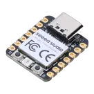
The Seeed Studio XIAO RP2040 is as small as the Seeed Studio XIAO SAMD21 but it's more powerful. On one hand, it carries the powerful Dual-core RP2040 processor that can flexible clock running up to 133 MHz which is a low-power microcontrollers. On the Seeed Studio XIAO RP2040 there is also 264KB of SRAM, and 2MB of on-board Flash memory which can provide more program to save and run. On the other hand, this little board has good performance in processing but needs less power.
All in all, it is designed in a tiny size as small as a thumb(20x17.5mm) and can be used for wearable devices and small projects. #wearableDevices #RP2040 #PICO #XIAO #SeeedStudio
Properties
Seeed Studios
Microcontroller
102010428
U
Pricing & Availability
Distributor | Qty 1 |
|---|
Controls
adsazad
copilot
- Connect the Positive Terminal of your adapter (typically +5V) to 5V:1.
- Connect the Negative Terminal of your adapter (GND) to GND:1.
Steps for Connection- Step 1: Verify your adapter's output is 5V.
- Step 2: Using a suitable connector or soldering, link the positive output of your adapter to the 5V:1 pin on your XIAO RP2040.
- Step 3: Connect the GND output of your adapter to the GND:1 pin on the XIAO RP2040.
Schematic Example Assumptions