nRF52810 Watch Template
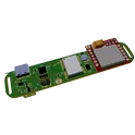
This is a smart watch project based on E73-2G4M04S1A module with SoC nRF52810 on board. OLED display and coin battery #wearable #nRF52810 #E73 #Ebyte #BLE #referenceDesign... show more0 Uses
0 Comments
0 Stars

Resonate Pendant
Resonate Pendant golden reference design. Board is a 39 mm x 63 mm portrait rectangle with 5 mm corner radii, 2-layer FR4, 0.8 mm thickness, 1 oz copper on both layers, matte black top solder mask, no bottom solder mask, ENEPIG finish, and no silkscreen on either side. Allowed components only: U1 STM32L052C8T6, U2 CH340E, U3 BQ24210DQCT, C1 10uF, C2 4.7uF, C3-C7 100nF, R1 24k, R2 1k, R3 10k, D1 green 0402 LED, MAG1-MAG4 magnetic pads, J1 solar solder pads, J2 battery solder pads, TP1-TP4 test pads. Required top artwork: golden-ratio grid lines and gold circles on F.Cu with mask openings, decorative only, 0.8-1.0 mm width, at least 0.5 mm from active traces. Required bottom artwork: exposed ENEPIG bottom copper split into FREQ_OUT 61.8 percent and GND 38.2 percent with an exact 0.20 mm S-curve isolation gap, no vias through bottom except one PA4-to-FREQ_OUT via at the extreme edge. Functional requirements: MAG1 and J1 VIN feed U3 IN, U3 OUT feeds J2 battery pad and system VBAT, MAG2 to U2 UD+, MAG3 to U2 UD-, MAG4 to common ground, U2 TX to U1 PA10, U2 RX to U1 PA9, U1 PA4 to bottom FREQ_OUT, U1 PA5 to R2 then D1 to GND, U3 ISET to R1 to GND, U3 TS to R3 to GND, decoupling exactly as specified. Prohibited items: external crystal, JST connectors, wireless module, antenna, separate regulator IC, ESD protection IC, USB-C connector, through-hole parts, bottom solder mask, silkscreen, more than three ICs, or any unapproved substitutions.... show more0 Uses
0 Comments
0 Stars
IoT Edge-Connector Placement Requirements
Requirements update for an IoT PCB module emphasizing compact placement around the main MCU and board-edge connector positioning for easier assembly. Includes mechanical constraints, connector orientation expectations, keep-out guidance, and acceptance criteria for the next layout phase.... show more0 Uses
0 Comments
0 Stars
TB6612FNG
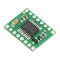
This tiny board is an easy way to use Toshiba’s TB6612FNG dual motor driver, which can independently control two bidirectional DC motors or one bipolar stepper motor. A recommended motor voltage of 4.5 V to 13.5 V and peak current output of 3 A per channel (1 A continuous) make this a great motor driver for low-power motors. #Module #Motor-Driver #TB6612FNG... show more0 Uses
0 Comments
0 Stars
HARDCORE PTAR cf62
2 ADS1115 powered by MP1584EN Buck Converted Module... show more0 Uses
0 Comments
0 Stars
Sim Scada
SCADA Sensor Node v2.1 using a Heltec WiFi LoRa 32 V4 module with separate +5V and board-generated +3V3 rails, ADS131M08 8-channel ADC front end, TCA9548A I2C multiplexer, TMP102-based fan control, ULN2003A relay and fan driver, CT/pressure/analog/One-Wire/vibration/humidity/Qwiic/flow/digital sensor interfaces, relay outputs, fan connector, brownout sensing, and a 200 mm x 140 mm 2-layer layout with Heltec keepout, antenna clearance, mounting holes, and DIN-rail slots.... show more0 Uses
0 Comments
0 Stars
RFID-RC522
Datasheet-driven MFRC522 RFID reader PCB intended to replicate RC522 module behavior at 13.56 MHz with a 3.3 V nominal supply, 2.5 V to 3.3 V operating range, and RC522-style 8-pin host header compatibility. The MFRC522 datasheet is the authoritative source for pin usage, power rail relationships, oscillator requirements, reset/IRQ handling, and antenna interface topology. AVDD, DVDD, and TVDD must be tied to the same 3.3 V rail; PVDD must be equal to or lower than DVDD; unused MFIN must be tied to SVDD or PVSS; SVDD must be tied to a valid supply if not used independently. The design must use a 27.12 MHz crystal meeting CL 10 pF and ESR <= 100 ohms, local 100 nF decoupling on each MFRC522 supply grouping plus bulk capacitance, and an RF front-end based on the MFRC522 application diagram and reference reader matching/tuning network. PCB priorities are short crystal and RF connections, compact placement of decoupling capacitors at supply pins, solid ground reference, and protected antenna region with minimal digital routing through the RF area.... show more0 Uses
0 Comments
0 Stars
vibrational sensor
Arduino-based vibration sensor module with SSD1306 OLED display for real-time vibration readings... show more0 Uses
0 Comments
0 Stars
Yodelling Olive Heat-Ray
Self-Powered RF Transceiver Module for EM Sensing with RF Prescaler, Divider Chain, and ESP32-S3 Interface... show more0 Uses
0 Comments
0 Stars
Pet Tracker Device
This is a Pet Tracker Reference Design based on STM32L4. Tracker connects with network by SIM800L module connected to the STM. Also MCU connected to the GPS by uart and send data to server #STM32 #GPS #G4 #G3 #LTE #IoT #Tracker #smartHomeDevices #referenceDesign #edge-computing #edgeComputing #stm #template #referenceDesign... show more0 Uses
0 Comments
0 Stars
Pet Tracker Device
This is a Pet Tracker Reference Design based on STM32L4. Tracker connects with network by SIM800L module connected to the STM. Also MCU connected to the GPS by uart and send data to server #STM32 #GPS #G4 #G3 #LTE #IoT #Tracker #smartHomeDevices #referenceDesign #edge-computing #edgeComputing #stm #template #referenceDesign... show more0 Uses
0 Comments
0 Stars
starter ec7b be93
USB-C Digital Compass Module with STM32, HMC5883L, TM1637 Display, and Enhanced Power Protection (JLCPCB-Ready)... show more0 Uses
0 Comments
0 Stars
Seeed Studio XIAO nRF54L15 Sense
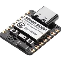
XIAO-Compatible 915MHz RF Shield with Wio-LR1121 Module and u.FL Interface... show more0 Uses
0 Comments
0 Stars
Melodic Moccasin Speeder Bike
AeroHUD VariScope Mark 1 - ESP32-S3 RF module vario/airspeed HUD with Qwiic OLED and SDP810, GPS, USB-C data+charging... show more0 Uses
0 Comments
0 Stars
starter ec7b 0150
USB-C Digital Compass Module with STM32, HMC5883L, TM1637 Display, and Enhanced Power Protection (JLCPCB-Ready)... show more0 Uses
0 Comments
0 Stars
starter ec7b
USB-C Digital Compass Module with STM32, HMC5883L, TM1637 Display, and Enhanced Power Protection (JLCPCB-Ready)... show more0 Uses
0 Comments
0 Stars
ESP32 Interface Board
Fortunate Moccasin Lightcycle - Added isolated AMS1117-3.3 regulator module (VIN/3V3/GND header) with input/output capacitors; not connected to existing nets... show more0 Uses
0 Comments
0 Stars

tint-test-bed
USB-C Digital Compass Module with STM32, HMC5883L, TM1637 Display, and Enhanced Power Protection (JLCPCB-Ready)... show more0 Uses
0 Comments
0 Stars

solder-mask-expansion-from-hole-edge-etc
USB-C Digital Compass Module with STM32, HMC5883L, TM1637 Display, and Enhanced Power Protection (JLCPCB-Ready)... show more0 Uses
0 Comments
0 Stars
Inherent Crimson Transporter
SmartDeskPet v1.0 Shield Stage 1 status: - Goal: 5V input -> dual AMS1117-3.3 rails (+3V3_MCU and +3V3_WIFI) with common GND. - Note: Keep power nets explicitly named (avoid unnamed nets) to keep ERC happy. Stage 1 completion checklist: - Mark J1 Pin_1 (+5V) as a Power Output pin to satisfy ERC power-driver checks. - Verify all GND symbols/returns are on the same GND net. - Keep +5V_SERVO isolated from the main +5V net (only share GND). Stage 2 preparation notes (MPN/LCSC + layout constraints): - MPN/LCSC targets to define before Stage 2 exit: - AMS1117-3.3 (SOT-223): set exact MPN and (optionally) LCSC PN for both U1 and U2. - 100nF capacitor (0603): set MPN/LCSC for all 0603 100nF decouplers. - 4.7k resistor (0603): set MPN/LCSC for I2C pull-ups R1 and R2. - 1000uF bulk capacitor (radial): set MPN/LCSC for C7 (CP_Radial_D10.0mm_P5.00mm). - DC005 power jack/regulator input: select exact DC005 footprint + MPN/LCSC (if used). - 2.54mm headers/sockets: set MPN/LCSC for H1, H2, J1, J3, J4, J5, P3, P4, P5, and J2. - ESP-01S antenna keepout: - Reserve a copper keepout under and in front of the ESP-01S onboard antenna. - No copper pours/traces/components in the antenna region (top and bottom) per module guidelines. - H1/H2 header spacing: - Maintain 1000 mil spacing between H1 and H2 header centerlines (shield mechanical requirement). - Silkscreen placeholders: - Add silkscreen labels for: 5V IN, GND, +3V3_MCU, +3V3_WIFI, SERVO1, SERVO2, I2C SDA/SCL, DHT11, ASRPRO UART2, ESP-01S UART3. - Add placeholder text for: MPN, LCSC, board revision, and date code. Stage 3 layout constraints (placement and routing guidance): - Connector placement strategy: - Place H1 and H2 first to lock the shield mechanical interface; enforce 1000 mil spacing. - Place J1 and any DC005 input at the board edge for easy access. - Designated power area planning: - Group U1, U2, and C7 near the 5V entry point; keep high-current 5V and regulator loops short. - Use wide copper for +5V and any servo supply; stitch GND around power section. - Antenna keepout boundaries: - Place J2 (ESP-01S socket) at a board edge with the antenna facing outward. - Enforce a top-and-bottom copper keepout in the antenna region; keep noisy power traces away.... show more0 Uses
0 Comments
0 Stars

starter 866d
USB-C Digital Compass Module with STM32, HMC5883L, TM1637 Display, and Enhanced Power Protection (JLCPCB-Ready)... show more0 Uses
0 Comments
0 Stars
Architectural Lavender Translation Collar
Architectural Lavender Translation Collar – ESP32‑S3 Wi‑Fi + LoRa, USB‑C, Li‑ion, low‑power design Overview Experience a cutting-edge IoT solution with this low‑power board built around the ESP32‑S3‑MINI‑1‑N8. Designed for seamless Wi‑Fi (2.4 GHz), BLE, and LoRa (868 MHz) connectivity, this board integrates ENS161 and ENS210 sensors over I2C alongside an RFM95W‑868 LoRa radio on SPI. It is powered via a 3.7 V Li‑ion cell with USB‑C charging up to 500 mA, complete with full battery protection, a robust 3.3 V rail tailored for Wi‑Fi burst currents, and per‑peripheral power gating to enhance energy efficiency. Core Features • MCU: ESP32‑S3‑MINI‑1‑N8 equipped with an onboard PCB antenna for 2.4 GHz Wi‑Fi/BLE, ensuring optimal wireless performance. • Sensors: Integrated ENS161 and ENS210 sensors utilize a shared I2C bus with controllable 4.7 kΩ pull‑ups for streamlined communication. • LoRa Radio: The RFM95W‑868 module, connected via SPI, enables long‑range communication at 868 MHz. Power & USB‑C Connectivity • Battery: A reliable 3.7 V 1200 mAh Li‑ion battery connected via a right‑angle JST‑PH 2‑pin connector features built‑in battery protection. • Charging: The USB‑C receptacle, with CC resistors and TVS protection on D+/D− along with series resistors, supports fast, safe charging with a current limit of 500 mA. • Regulation: A dedicated 3.3 V regulator capable of handling Wi‑Fi burst currents coupled with bulk and high‑frequency decoupling ensures stable operation, supported by status LEDs indicating power and charge states. Low‑Power Control • Peripheral Management: Load switches allow selective power‑gating of the ENS161, ENS210, and RFM95W modules, controlled directly by ESP32‑S3 GPIOs. • Energy Efficiency: Controllable I2C pull‑ups minimize idle current, vital for prolonged battery life in IoT applications. RF and Antenna Integration • 2.4 GHz: Utilizes the integrated PCB antenna on the ESP32‑S3 with proper ground/metal keep‑out zones for optimal signal integrity. • 868 MHz: Features a controlled‑impedance feed from the RFM95W to a PI matching network (C‑L‑C pads) with flexible antenna options—selectable via SMA connector, chip antenna, or PCB trace—and includes RF ESD protection. Connectivity & Debug Features • USB‑C Interface: Provides secure data connectivity with integrated safeguards and proper terminations. • Debugging: A comprehensive programming/debug header exposes EN, BOOT, and UART lines, with test points on key rails and buses (3V3, VBAT, SCK, MOSI, MISO, SDA, SCL, RESET/EN, GND) to simplify development and troubleshooting. Design Verification • Rigorous ERC/DRC and decoupling checks ensure adherence to component ratings and optimal signal routing. • Maintain RF keep‑outs and impedance‑controlled traces for both 2.4 GHz and 868 MHz paths, securing reliable performance even during high‑intensity operations. #IoT #ESP32S3 #LoRa #LowPowerDesign #USB-C #WirelessConnectivity #BatteryPowered #RFDesign... show more0 Uses
0 Comments
0 Stars
starter 7bf3
USB-C Digital Compass Module with STM32, HMC5883L, TM1637 Display, and Enhanced Power Protection (JLCPCB-Ready)... show more0 Uses
0 Comments
0 Stars
net-label-demo
USB-C Digital Compass Module with STM32, HMC5883L, TM1637 Display, and Enhanced Power Protection (JLCPCB-Ready)... show more0 Uses
0 Comments
0 Stars