Chat
Welcome to Flux
Treat Flux like your intern. Tell it what you'd like to build and it'll get to work. You can also ask it questions, brainstorm ideas, and teach it your preferences. Learn More
Explain this part
Write a part description
Describe each pin
Verify Part Details
Recommend similar parts
Check availability & lifecycle
J1
New Comment
3
Can you check if I am missing any connections to J1. The application is for USB ...

3y
From the netlist and components provided, it appears that the following pins on J1 are connected:
- GND1, GND2, GND3, GND4
- VBUS1, VBUS2, VBUS3, VBUS4
- D1+, D1-
- CC1, CC2
- SHIELD (all 4 instances)
The CH340G's application of USB to Serial typically requires the following connections:
- VBUS (to power)
- GND
- D+ and D- (for data transmission)
For a USB-C connector (like J1, with part number 1054500101), the following pins are typically used:
- VBUSx
- GNDx
- D1+, D1-
- SHIELD
- CC1, CC2
Since your current connections match these requirements, it seems like you're not missing any required connections for a basic USB to Serial application using the CH340G.
The remaining pins on this USB-C connector (RX1-, RX1+, RX2-, RX2+, SBU1, SBU2, TX1-, TX1+, TX2-, TX2+) are not typically used in a USB to Serial application and can be left unconnected or connected to No Connect for clarity.
Please note that this does not account for any specific requirements your design might have outside of a basic USB to Serial application.
Here's the connections to No Connect for the unused pins:
- Connect J1:RX1- to No Connect.
- Connect J1:RX1+ to No Connect.
- Connect J1:RX2- to No Connect.
- Connect J1:RX2+ to No Connect.
- Connect J1:SBU1 to No Connect.
- Connect J1:SBU2 to No Connect.
- Connect J1:TX1- to No Connect.
- Connect J1:TX1+ to No Connect.
- Connect J1:TX2- to No Connect.
- Connect J1:TX2+ to No Connect.
3y
Yeah please wire the unused pins of J1 to no connect for me
3y
Sure, here's how to wire the unused pins of J1 to No Connect:
- Connect J1:RX1- to the NC net.
- Connect J1:RX1+ to the NC net.
- Connect J1:RX2- to the NC net.
- Connect J1:RX2+ to the NC net.
- Connect J1:SBU1 to the NC net.
- Connect J1:SBU2 to the NC net.
- Connect J1:TX1- to the NC net.
- Connect J1:TX1+ to the NC net.
- Connect J1:TX2- to the NC net.
- Connect J1:TX2+ to the NC net.
This will ensure that these pins are explicitly marked as not connected in your design.
3y
2
How do I connect my USB-C port to the CH340G IC?
2y
Planning ...
2y
To connect your USB-C port to the CH340G IC, you first need the following components: a USB-C cable, a USB-C breakout board, the CH340G IC, and suitable connectors for your PCB (print -circuit board).
Here is one approach to make the connection:
-
Using the USB-C cable, connect one end to the USB-C port on your device.
-
Connect the other end of the USB-C cable to the USB-C breakout board. This board should convert the USB-C signals into signals compatible with the CH340G. Locate the D+ and D- signals on the breakout board.
-
Connect the D+ and D- signals from the breakout board to the corresponding D+ (pin 3) and D- (pin 2) inputs on the CH340G IC.
Please refer to the specific datasheet for your version of the CH340G IC for precise pin descriptions, as connections may vary depending on the specific chip version. For the USB-C breakout board, also, make sure to refer to its specific datasheet to properly identify the D+ and D- signals.
Remember that the CH340G needs proper voltage supply, ground connections and also crystal circuit connected to work correctly as a USB to serial converter. You should ensure that all these connections are correctly applied (according to the information given on the CH340G datasheet).
It's important to notice that USB-C cables and ports support higher power delivery than other USB types. Ensure any device that you connect to the USB-C port is capable of handling the power it delivers.
The information provided does not specify if there is any direct device-to-device compatibility provided by the USB-C port and the CH340G IC, and some kind of interface or driver would be necessary for the IC to effectively 'read' and deal with the signals coming from the USB-C.
2y
4
VCC
RX
F1
Y1
TX
DTR
VCC
RTS
GND
VCC
C6
Capacitance
20pF
R5
Resistance
1kΩ
R7
Resistance
1kΩ
C7
Capacitance
0.01uF
D1
C8
Capacitance
10uF
R2
Resistance
2.1kΩ
R8
Resistance
1kΩ
R6
Resistance
1kΩ
R1
Resistance
2.1kΩ
C9
Capacitance
100nF
R3
Resistance
1kΩ
C5
Capacitance
20pF
C10
Capacitance
100nF
FUSE
D1+
RXD
D1+
IC2
D1-
TXD
D1-
No files yet
Reviews
Documents
Documents are markdown text files which describe project goals, capture details, or even simulation outputs.
Assets

ch340g-removebg-preview.png
ch340g-removebg-previewThumbnailCH340G Breakout USB-C
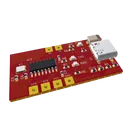
Custom CH340G Breakout
Properties
SUBLAYOUT
Pricing & Availability
Distributor | Qty 1 |
|---|---|
Digi-Key | $1.57–$3.57 |
LCSC | $1.20–$1.50 |
Mouser | $0.82–$0.90 |
Controls
Welcome 👋
Flux accelerates your PCB design with AI.
Create your account to start using this component and bring your ideas to life.