Chat


@file Extract the recommended operating conditions for this part project. Retrieve key parameters such as supply voltage range, operating temperature range, input/output voltage levels, and other relevant conditions specified for optimal performance.

explain this project.

@copilot explain this project.
2y
Sure, I'd be happy to explain this project based on the provided textual data.
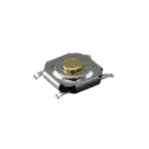
The project uses a tactile switch, specifically a SPST-NO (Single Pole Single Throw - Normally Open) top actuated surface mount switch. This switch is made by C&K and is of the PTS526 type. This type of switch typically comes in a small surface mount package, which means it's suited for automated PCB assembly. The SPST-NO terminology indicates that the switch connects its two terminals together when pressed.
Four designators (NO_2, COM_1, NO_1, COM_2) are mentioned, each one corresponds to a pin of the switch. Here's an interpretation of these designators:
  • NO_1 and NO_2 (Normally Open) would correspond to the two positions of the switch, i.e., connections made when the switch is pressed.
  • COM_1 and COM_2 (Common) could be the two common connections of the switch, i.e., the terminals that the NO_1 and NO_2 pins connect to when the switch is engaged.
In the current state of the project, no electrical connections have been made yet between these designators. It means you're in the initial steps of building your circuit and the next steps would be to define the connections between these pins and the other components or power and ground planes on your PCB.
Since there are no other components or specifications given, it's still an open book to what else you might be planning to add to this project.
2y
do i only need to connect to one of each set
2y
Typically, for a Single Pole Single Throw (SPST) type switch like PTS526, you would need to connect to only one 'NO' (Normally Open) terminal and one 'COM' (Common) terminal.
The common pin is usually connected to the circuit you want to control, and the NO pin is connected to the other end of the circuit which could possibly be power supply or another component of the circuit. When the tactile switch is pressed, it makes the connection between these two pins which completes the circuit.
In your project:
  • For NO terminals, you can choose either NO_1 or NO_2. Let's assume you choose NO_1.
  • For COM terminals, you can choose either COM_1 or COM_2. Let's assume you choose COM_1.
This means when the switch is not pressed, the circuit between NO_1 and COM_1 is open (i.e., the switch is in its "normally open" state). When the switch is pressed, the circuit between NO_1 and COM_1 is closed, allowing current to flow.
Please remember that although the switch has 2 sets of terminals, you would use only 1 set in most applications unless there's a special requirement to use both. If your project has such a requirement, let me know to provide a more specific instruction.
2y
Someone is typing...
2
NO_2
COM_1
NO_1
COM_2
Name
Pin #
Type
Current
Max Current
Part Type
Terminal Order
Terminal Type
COM_1
1
Passive
0.05A
0.05A
Terminal
unspecified
COM_2
2
Passive
0.05A
0.05A
Terminal
unspecified
NO_1
3
Passive
0.05A
0.05A
Terminal
unspecified
NO_2
4
Passive
0.05A
0.05A
Terminal
unspecified

PTS526 SM15 SMTR2 LFS

PTS526 SM15 SMTR2 LFS thumbnail