@copilot list all ICs and the decoupling capacitors attached to each.
Ensure to include all ICs present in the design, including digital ICs, power converters, LDOs, etc.
For every IC, clearly state:
What power net the decoupling capacitors are attached to. What is the stated voltage of that net.
The voltage rating and value of the attached decoupling capacitors.
Signal with the expression “[WARNING]” if any of the following conditions are met:
no decoupling capacitors are attached;
the voltage of the power net is higher than the voltage rating of the capacitor;
No voltage range was stated for the capacitor.
Give a separate “[WARNING]” for each condition. Signal with the expression “[OK]” if none of those conditions are met
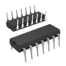
Given the provided project description, there is only one Integrated Circuit (IC) mentioned, which is the IR2110PBF Half-Bridge Gate Driver. However, the list does not include any decoupling capacitors directly attached to it or their specifications. Therefore, with the available information, here's the assessment:
Table
IC Designator
Power Net Attached
Voltage of Power Net
Decoupling Capacitor Value
Capacitor Voltage Rating
Status
IR2110PBF
-
-
-
-
WARNING No decoupling capacitors are attached.
Notes:
The IR2110 typically requires a connection to VCC (power supply for the logic part of the IC) and VDD (power supply for the gate driver part), with decoupling capacitors close to these pins to ensure a stable power supply and to reduce noise.
An ideal decoupling capacitor for an IC like the IR2110 might range from 0.1μF to 10μF, with a voltage rating comfortably above the operating voltage of the IC to ensure reliability.
Without specific decoupling capacitors listed or their voltage ratings and given that we're missing specifications on the power nets, it's not possible to provide the voltage of the power net or to directly compare it to a capacitor's voltage rating.
Recommendation:
Add decoupling capacitors to the VCC (pin 3) and VDD (pin 9) nets of the IR2110PBF. The lack of decoupling capacitors can lead to unstable operation or noise-related issues. Typical practice involves placing a small (e.g., 0.1μF) ceramic capacitor close to the IC pins for high-frequency decoupling and a larger (e.g., 10μF) capacitor nearby for lower-frequency stability.
Ensure the voltage ratings of these capacitors are higher than the power net voltages they are meant to decouple. This is critical for safety and reliability, especially in a power-driving application like that of the IR2110's.
Given the missing details about actual circuit implementation and capacitor specifics, my recommendations are based on common practices and typical applications of the IR2110 gate driver IC.
2y
Someone is typing...
2
list all LO pins in a table format. For each pin provide its pin number, pin nam...
peterdlo10
copilot
Table