Locating GPIO Pins on ESP32 Schematic

IC2 is the TMC6300-LA-T motor driver. Its hookup typically involves:
  1. Power Supply & Decoupling:
    • Ensure that its supply pins (for example, the main voltage inputs and VIO/NSTDBY) are connected to the correct power rails.
    • Add decoupling capacitors as specified in the datasheet on each power pin.
  2. Ground Connections:
  3. Control & Interface Signals:
    • Interface its control pins (such as DIAG, 1.8VOUT, U, BRUV, etc.) with your microcontroller (e.g., the ESP1) as needed.
    • Follow the datasheet recommendations for signal levels and required pull-up or pull-down resistors if applicable.
  4. Motor Outputs:
    • If you’re driving a motor, make sure the output pins are routed to your motor circuitry along with any necessary current sensing or protection components.
Could you please clarify which particular aspect of the hookup you need help with? For example:
  • Wiring the power and decoupling network for IC2
  • Interfacing its control pins with the ESP module
  • Routing motor output connections
Let me know and I can provide more specific guidance.
Specify hookup details needed
Decoupling capacitor placement
Connect motor outputs
USB1
U1
D2
D1
C4
Capacitance
10uF
ESP_RX
CC1
C3
Capacitance
10uF
GPIO2
TOUT
USBDP
ADC
C11
Capacitance
0.1uF
ESP_RX
USBDN
GPIO15
GPIO14
C8
Capacitance
10uF
ESP_TX
USBDP
CC2
ESP_EN
ESP_IO0
USBDN
GPIO14
GPIO4
ESP_IO0
C6
Capacitance
0.1uF
C7
Capacitance
0.1uF
GPIO16
GPIO5
CC1
USBDP
GPIO13
TOUT
GPIO12
GPIO15
ADC
C10
Capacitance
0.1uF
USBDN
ESP_RX
C2
Capacitance
0.1uF
C1
Capacitance
0.1uF
GPIO4
ESP_TX
USBDN
ESP_EN
GPIO12
USBDP
C12
Capacitance
0.1uF
ESP_IO0
GPIO2
RST
RST
CC2
GPIO16
USBDN
GPIO5
GPIO13
ESP_TX
ESP_EN
ESP_IO0
ESP_EN
USBDP
+3V3
ESP1
VBUS
R1
Resistance
Resistance
Resistance
10kΩ
R8
Resistance
Resistance
Resistance
82kΩ
+3V3
PWR
R7
Resistance
Resistance
Resistance
220kΩ
R2
Resistance
Resistance
Resistance
5.1kΩ
+3V3
C9
Capacitance
10uF
R4
Resistance
1kΩ
+3V3
R3
Resistance
Resistance
Resistance
5.1kΩ
+5V
C5
Capacitance
10uF
+3V3
VBUS
+5V
+3V3
+3V3
+3V3
R6
Resistance
Resistance
Resistance
10kΩ
+5V
R5
Resistance
Resistance
Resistance
10kΩ
+3V3
EN
Q1
J2
J1
BOOT
IC2
IC1
Q2

No files yet

Documents

    Documents are markdown text files which describe project goals, capture details, or even simulation outputs.

    Assets

    ESP-WROOM-02U Reference Design-removebg-preview.png

    ESP-WROOM-02U Reference Design-removebg-preview.png

    ESP-WROOM-02U Reference Design-removebg-previewThumbnail

    ESP-WROOM-02U Reference Design

    ESP-WROOM-02U Reference Design thumbnail
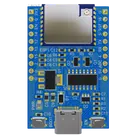
    This project is a reference design for an ESP-WROOM-02U based device. It features USB-C for power and data transfer, onboard voltage regulation, and multiple peripheral connections. It also includes a CH340C for USB to serial conversion #referenceDesign #project #ESP8266 #WROOM #RF #WIFI #MCU #referenceDesign #simple-embedded #espressif #template #reference-design

    Pricing & Availability

    Distributor

    Qty 1

    Arrow

    $1.74–$2.37

    Digi-Key

    $2.01–$11.27

    LCSC

    $3.45–$4.12

    Mouser

    $5.03

    Verical

    $0.07–$0.26

    Controls