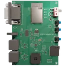
ESP32 Retro PC Project Overview
Thought for 4 mins 9 sec
Here’s a structured walkthrough of your “ESP32 x86 PC” project.
Project purpose
- A self-contained “retro PC” platform built around the ESP32, exposing classic PC-style IO: VGA video, PS/2 keyboard/mouse, audio-out to a speaker, microSD storage, plus USB-C for power and USB-UART for programming/debug.
- It ties these interfaces into the ESP32-WROVER-E’s compute, storage, and IO so it can emulate/replicate vintage PC functionality.
Core blocks and how they interact
Block overview
Table
| Block | Components | What it does | Key interactions |
|---|---|---|---|
| MCU/Compute | ESP1 (ESP32-WROVER-E) | Main processor, Wi-Fi/BLE-capable module, drives VGA, SDIO, PS/2, audio | Powered from 3.3 V LDO; interfaces to USB-UART, SD card, VGA, audio amp, PS/2 |
| USB-C power + USB-UART | USB1, IC1 (CH340C), D2, R2, R3, D3, D4, D5 | USB-C provides VBUS power and a USB 2.0 data link to the CH340C (USB-UART). TVS arrays protect D+/D-. CC resistors set device-mode attach | CH340C connects to ESP32 UART0 (TXD0/RXD0) and drives auto-boot via transistors |
| Power regulation + protection | POWER, D1, U1, bulk/decoupling caps C5, C9, many 0603 caps | VBUS -> slide switch -> Schottky diode -> 3.3 V LDO -> +3V3 rail; local decoupling throughout | Feeds ESP32, SDIO rail, logic, audio front-end, etc. |
| Auto-program/boot control | Q1, Q2 (BSS138) + buttons BOOT, RESET | CH340C RTS/DTR toggle EN/IO0 via MOSFETs for auto download mode; manual buttons provided | Ensures smooth flashing and reset of ESP32 |
| VGA output | VGA + series/passive network | ESP32 GPIOs generate HSYNC/VSYNC and simple resistor-DAC RGB to DE-15 | Direct from ESP32 pins; relies on precise timing firmware |
| PS/2 keyboard & mouse | KeyBoard, Mouse, level-shifters Q3, Q5, Q6, Q7 | Provides 5 V to PS/2 and uses MOSFET level shifting for open-collector CLK/DATA into ESP32 | Pull-ups on the 5 V side, translated to 3.3 V-safe levels for ESP32 |
| microSD (SDIO) | Card2, pull-ups R56, R57, R58, R54, R50, ESD D3, D4, D5 | SDIO interface with proper pull-ups and ESD protection | Powered from SDIO_3V3; connects to ESP32 high-speed IO |
| Audio output | Amp U2 (NS4150B), speaker SPK1, input filter R19/R20/caps, ferrites L1/L2, output chokes FB1/FB2, bulk C16 | ESP32 DAC GPIO feeds a BTL/Class-D audio amp; LC/RC networks tame EMI and stabilize load; separate audio ground domain | Analog/digital ground segregation (AU_GND) and ferrites reduce noise coupling |
| UX & indicators | PWR LED, test points TX, RX, EN, IO0, GND, 3V3 | Visual power indication; easy probing/programming | Ties into power and UART/boot control nets |
Signal/power flow highlights
- Power path: USB1 VBUS -> POWER switch -> D1 Schottky -> U1 3.3 V LDO -> +3V3 to ESP1, SDIO rail, logic, audio input stage. Large/small caps (C5, C9, many 0603 ceramics) buffer transients.
- USB-UART: IC1 connects D+/D- from USB1 with ESD D2; TXD/RXD link to ESP32; Q1/Q2 translate RTS/DTR into EN/IO0 sequencing for auto-boot; buttons BOOT/RESET provide manual control.
- Video: ESP1 GPIOs drive HSYNC/VSYNC and RGB through a simple resistor DAC to VGA.
- PS/2: The 5 V on the connectors KeyBoard/Mouse is translated to 3.3 V logic using BSS138 open-drain level shifters Q3, Q5, Q6, Q7 — appropriate for bidirectional clock/data.
- Storage: Card2 uses ESP32 SDIO with pull-ups (R56, R57, R58, R54, R50) and line ESD (D3, D4, D5).
- Audio: ESP32 DAC (GPIO25) is conditioned then amplified by U2 to drive SPK1. Ferrites L1/L2 and a separate audio ground domain reduce coupling into digital ground.
Key technologies, dependencies, and design choices
- ESP32-WROVER-E as the single-chip “PC”: leverages dual-core MCU, fast GPIO, and built-in DAC/SDIO to synthesize VGA, audio, and storage.
- USB-C as power and data: CC resistors (R2, R3) must be set for a USB2.0 device. Knowledge-base guidance: include TVS on USB data lines; you did (D2); keep capacitance low on D+/D-.
- LDO-based 3.3 V rail: U1 is simple and quiet, but trades efficiency/thermal headroom against ease of use. Wi-Fi current bursts need bulk and local decoupling near the ESP32.
- Open-drain MOSFET level shifting (BSS138): Ideal for PS/2’s bidirectional, open-collector signals; avoids active bus drivers that could fight the line.
- Split analog ground for audio: Audio nets return to AU_GND with ferrites and output filtering (FB1, FB2), which mitigates ground bounce and switching noise coupling.
- SDIO pull-ups and ESD: SD spec requires specific pull-ups; you’ve implemented them and added ESD on command/data/clk lines, supporting reliability.
Trade-offs and optimizations
- LDO vs switching regulator: LDO (U1) is low-noise and simple, but can run hot at higher USB voltages and load currents; a buck would improve efficiency and thermal margin at the cost of EMI and complexity.
- VGA via resistor DAC: Extremely low-cost; constrained color depth and relies on tight timing from firmware. Great for retro graphics, not for high-resolution/color-fidelity use.
- Class-D/BTL speaker amp: Efficient, compact, and loud for size; requires good filtering, short high-current loops, and careful ground strategy to avoid audio hiss and EMI.
- BSS138 level shifting: Reliable for open-drain PS/2; not suited for actively driven push-pull buses (you avoided this, which is correct).
Potential challenges and performance considerations
- USB-C attach/CC: Ensure R2/R3 are correct for device-mode so 5 V is advertised to the board. Low-capacitance ESD elements are advisable on D+/D- (you have D2).
- LDO thermal headroom: With Wi-Fi bursts and multiple peripherals, verify worst-case power dissipation of U1 and ambient temperature; keep bulk caps close to the ESP32 rail to ride through TX peaks.
- SDIO signal integrity: Keep pull-ups close to the socket, route length-matched lines, and consider series damping resistors at the source if ringing appears at higher SDIO speeds.
- Audio noise/EMI: Maintain short, symmetric output filter traces; keep the LC network close to U2; stitch AU_GND to main ground at a single, controlled point to prevent ground loops.
- VGA timing margin: ESP32 firmware must tightly schedule HSYNC/VSYNC and pixel timing; GPIO drive plus resistor DAC limits max resolution/color depth.
- PS/2 robustness: Ensure adequate pull-ups on the 5 V side and clean edge rates; keep clock/data pairs short and away from noisy nets.
Real-world applications
- Retro-computing emulator with real VGA and PS/2 peripherals.
- Embedded UI system with local display and input.
- Educational platform demonstrating multi-interface MCU design (USB, SDIO, VGA, audio, PS/2).
Suggestions for improvement and future enhancements
- Power: Consider a small synchronous buck to 3.3 V ahead of — or instead of — the LDO for cooler operation and higher load headroom. Add a polyfuse on VBUS and a transient suppressor on 5 V input if you expect hot-plug stress.
- USB robustness: Add a common-mode choke on D+/D- and ensure the TVS (D2) capacitance is within USB 2.0 budgets; verify CC resistor values are correct for device role.
- ESP32 decoupling/boot: Ensure EN has a defined pull-up and small cap for noise immunity (knowledge suggests a pull-up plus 0.1 µF on EN is good practice). Place 100 nF decouplers at each VDD pin cluster.
- Audio domain: Maintain a single-point tie between AU_GND and digital ground; if hiss persists, consider an LC/ferrite on the amp’s supply and star-route the speaker returns to AU_GND.
- SD card: If running 4-bit SDIO at higher speeds, keep lines short and matched; optionally add small source series resistors to reduce edge ringing.
- EMC: Review high di/dt loops (amp outputs, USB 5 V ingress) and keep them tight; consider ground guard traces near VGA HSYNC/VSYNC if cross-talk appears.
- Features: Add a headphone jack with line-level buffer; add a selectable external clock for more stable VGA timings; add small SPI flash or PSRAM expansions if firmware needs it.
If you want, I can dive into any block (e.g., SDIO, USB-C, audio, or VGA) and review the exact connections and component placements to recommend concrete layout or component-value tweaks.
Dive into power design
Detail USB-C section
Review audio/grounding
Analyze SDIO interface
Evaluate VGA implementation