Arduino RGB LED Schematic
Create a schematic with the following components and connections:
Components:
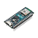
Arduino Nano ESP32
RGB LED (common cathode)
3x resistor 220Ω
1x resistor 10kΩ
photoresistor (LDR)
LCD 16x2 with I2C module (PCF8574, address 0x27)
Connections:
Arduino D9 → 220Ω resistor → LED red anode
Arduino D10 → 220Ω resistor → LED green anode
Arduino D11 → 220Ω resistor → LED blue anode
LED common cathode → GND
Arduino 3.3V → photoresistor pin 1
photoresistor pin 2 → Arduino A1
photoresistor pin 2 → 10kΩ resistor → GND
Arduino A4 (SDA) → LCD SDA
Arduino A5 (SCL) → LCD SCL
Arduino VBUS (5V) → LCD VCC
Arduino GND → LCD GND
16 days
0:29
Creating a project link.
Creating a schematic link.
You want a schematic that wires an Arduino Nano ESP32 to an RGB%20LED%20(common%20cathode), Generic Resistor parts, a photoresistor%20(LDR), and an LCD%2016x2%20with%20I2C%20module%20PCF8574%200x27.
You’re currently viewing a part project for ABX00083, not an editable design workspace, so the fastest path is to start a new project with your full schematic request prefilled. The current project is the Arduino board’s part definition, with MPN ABX00083 and datasheet URL already set in its properties
Click that link and Copilot will continue in a fresh editable project with your full request loaded.
Create new project
Add pull-ups too
Use labels clearly
16 days


Welcome 👋
Flux accelerates your PCB design with AI.
Create your account to start using this component and bring your ideas to life.
alpex
copilot